I have written a few posts about Geometric Dimensioning and Tolerancing (GD&T) basics and I want to write another one about a topic that is probably the most often question asked of me: Zero Tolerance dimensions. The name Zero Tolerance is confusing to some folks because as we all know "every dimension must have a tolerance" so what is a Zero Tolerance dimension? Does that mean that the part has to be perfect? Why would anyone put a Zero Tolerance on a drawing? I'm going to try and answer those questions in simple steps starting with a quick review of Material Conditions because you can't have a Zero Tolerance on a drawing without specifying a Material Condition. If you haven't read my other posts about Geometric Dimensioning and Tolerancing I suggest that you do by clicking HERE and reading the posts related to GD&T. At a minimum read the posts about Material Condition and True Position. One thing I want to mention is my intent here is to explain the concepts in simple terms and avoid all the esoteric 'advanced concepts' that you will find in other places on the net. I get questions from friends and colleagues who are not familiar with GD&T and I try to answer those questions as simply as I can. Once someone understands the basics the more complex concepts are easier to get. If you are not familiar with a Zero Tolerance here is a drawing that is using it.
 |
| Drawing With Zero Tolerance |
Before I start talking about Zero Tolerances I want to talk briefly about Material Condition because the concept of material condition is key in understanding Zero Tolerances. I'm going to go fast so if you want a better and more detailed explanation of Material Conditions read THIS post that I did awhile ago. Here we go! The Material Condition concept is a fancy way to think about how big or small a particular Feature of a part is. There are three material conditions and two types of Features. The three Material Conditions are: Maximum Material Condition or MMC, Least Material Condition or LMC and Regardless of Feature Size or RFS. The two types of Features are: Internal (like a hole) and External (like a block). When considering Zero Tolerances the only Material Conditions that are important and MMC and LMC so I'll skip RFS here.
An easy way to think about MMC and LMC is to think "Worst Case" because that is what they mean. When you measure a part and every dimension is at LMC or at MMC the part is at it's extremes of tolerances or the Maximum size or Least size that it can be in. Why not say "the biggest size" for MMC and "smallest size" for LMC you ask? Because biggest and smallest depends on what kind of feature it is! Think about an Internal feature like a hole. When you add material to a hole it gets smaller. When you take material away from a hole it gets bigger. So think about a hole and add material to it until it gets as small as it can be and that is the Maximum Material Condition. Let's say a drawing dimensions a hole at 1.500 +/-.005 in diameter. The smallest the hole can be is 1.495 and that is the hole's Maximum Material Condition (add material and it gets smaller). The Least Material Condition for that hole would then be 1.005 (remove material and it gets bigger). In the case of an external feature it's the opposite. Add material to a block it gets bigger, remove material and it's smaller. If a block is 4.000 +/-.005 and you add material to it until it's 4.005 wide then it's at its Maximum Material Condition.
So MMC is when a features dimensions are at one extreme of it's size tolerance and LMC is when it's at the other extreme. The 'extreme' depends on whether it's an Internal Feature or and External Feature and extreme is the worst case because it can't get any bigger (or smaller) than that!
To summarize: (I'm saying it again because it's important!)
Maximum Material Condition (MMC) is when you have the Maximum amount of material that is allowed by a features tolerance. If you add material to a Internal Feature like a hole, the hole gets smaller. If you add material to an External Feature like a block it obviously gets bigger. An example of this is in the top of the picture below. The 1.500 +/-.005 diameter hole is 1.495 in diameter at MMC. The hole can't be any smaller than 1.495 because it's a 1.500 +/-.005 diameter hole and 1.495 is as small as it's allowed to get.

Least Material Condition (LMC) is just the opposite of MMC. Least Material Condition means that you you have the Least amount of material that is allowed. If you remove material from an Internal feature like a hole it gets bigger. And if you remove material from an External Feature like a block it gets smaller. An example of this is in the bottom of the picture above. The 1.500 +/-.005 diameter hole is 1.505 in diameter at LMC.
Understanding that MMC and LMC are "Worst Case" and what they mean in relation to Internal Features and External Features is important to understanding Geometric Dimensioning and Tolerancing generally and especially Zero Tolerancing.
So how do MMC and LMC change the way Position Tolerancing works? Take a look at the picture below that shows a plate with a hole in it. I didn't put the dimensions showing where the hole is on the plate on purpose because they don't matter in this example. The hole is Positioned with a diametrical tolerance of 0.010 at MMC (the M with a circle around it). So when the hole is at MMC (1.495 in this case) the tolerance of position is 0.010, the hole would have to be located within a 0.010 area around the nominal position (wherever that is, it doesn't matter). But what if the hole isn't at MMC? What if the hole is bigger than 1.495 in diameter, after all it can be as big as 1.005?
 |
| Position Tolerance with Maximum Material Condition |
Another way to look at this is imagine how the real world works. If the drawing for a part looks like the drawing above and you have a box of parts in front of you that you are measuring to see if they are to print, the first thing that you would have to do to see if the part was made correctly is measure the diameter of the hole. So measure the hole! Let's say that the first part that you measure has a hole in it that is 1.495 in diameter. That is the MMC diameter of the hole because the is the smallest size that the hole can be. Now that you know how big the hole is you can measure the location of the hole.

Because the hole is at it's MMC size as stated in the Feature Control Frame, the position of the center of the hole would have to be within a .010 area around where the hole is located. The tolerance of position for the hole is .010 because the hole is at MMC.
But wait! "What if the hole isn't at MMC, then what?" Lets say that the next part that you take out of the box has a hole that is 1.497 in diameter. How close does that parts hole have to be to it's nominal position? A diameter of 1.497 is .002 away from the 1.495 so in this case you add the difference to the total tolerance and get 0.012. What?!?! In other words the MMC diameter is 1.495 and the actual diameter is 1.497 so you have .002 'left over' and can add that .002 to the position tolerance to get .012 total position tolerance!!

In this case the hole is a little bit bigger than it's MMC size so it's acceptable position is also a little bit bigger. The farther the actual diameter of the hole departs from it's MMC dimension on the drawing the farther it's actual position can depart from the nominal in the feature control frame.

The last part that comes out of the box has a hole that is 1.505 in diameter. The diameter was the first dimension that was measured and it is 1.505 or 0.010 away from the MMC dimension of 1.495. So add the Feature Control Frame tolerance of 0.010 to the difference between the actual dimension and the MMC dimension ((1.505 actual - 1.495 MMC = .010) + 0.010 FCF) and you get 0.020.
Why use dimensioning like this?
What is going on here is the bigger the hole gets, the farther it can be from it's nominal position. This is how life works! How many times have you drilled a hole in something and then tried to put it in place and get a bolt through the hole - and it doesn't fit!! The hole is the right size but it's a little bit "off" position so the holes don't quite line up and the bolt doesn't go through both pieces. What do you do? You drill one hole out a little bit bigger so the bolt can go through! Because the hole is a little bit off position you have to make it a little bit bigger to get the bolt to go through and line up. How far out of position the hole is determines how big you drill out the hole to make it work. Dimensioning a drawing using a Positional tolerance and specifying a Material Condition is the same idea. The drawing is saying that when the hole (or any feature) is exactly at it's worst case dimension (MMC or LMC) then it's position has to be within the Feature Control Frame tolerance. If the feature isn't at it's worst case dimension (you've drilled it out in the case of a hole) it can be a little bit off position.
Now for the big question, what does Zero Tolerancing mean? Zero Tolerancing is the same idea as in the above drawings, in fact I'm going to use the exact same drawings to show what it means except in this case I'll specify a zero tolerance of position. In the above drawings "The bigger the hole gets, the farther it can be from it's nominal position" and the same is true with Zero Tolerancing. The only difference is with Zero Tolerancing the nominal position is zero! How does that work?
Think again back to the real world and you are trying to drill a hole in something and you want to it line up perfectly. The hole that you are drilling is the same size as the bolt and the hole that you trying to line up with is also the same size as the bolt. What do you do? Ideally you can "match drill" the hole to the part that it has to fit to. Line both parts up and put the drill through both, that way you get holes that are exactly the right size are lined up exactly. If somehow you happen to get the drilled hole a little off then it has to be a little bigger. This is more or less the idea of zero tolerancing. Have a look at the below drawings below to see what I mean.
 |
| Zero Tolerance of Position |
In the above drawing the tolerance of position is zero in the Feature Control Frame and the hole is at MMC. The hole can't get any smaller so the position of the hole can't be off perfect at all. That is a Zero Tolerance. Just like "match drilling" a hole, the hole has to be perfect if it's at at's smallest size. Of course we all know that in the real world we can't be perfect so what if the hole is a couple of thousands larger?

The hole is .002 larger than the MMC size so it's allowed to be .002 off it's nominal position. Just like in the above drawings where the hole was .012 off nominal (.010 in the Feature Control Frame + .002 in size) here it's off by the same amount (.000 +.002) and the bolt still fits!

In the above picture the hole is at it's LMC of 1.005 or the largest size that it is allowed to be because of it's size tolerance (1.500 +/- .005). Because of that it can be tolarance it can be out of position (with a tolerance of 0.000) of 0.010. Why is that? Because the total tolerance of size of the hole is 0.010 (+/-.005 * 2=.010).
This might seem confusing but really the tolerance of position in these cases is equal to the total tolerance of position (+/- .005 =.010) plus the tolerance of size of the feature (+/- .005 =.010) so just add them up. If the tolerance of position for the feature in the Feature control Frame is zero then the total tolerance of position is equal to the tolerance of size of the feature. Easy? Simple?
All that stuff above was about Zero Tolernacing at MMC and match drilling, bolts fitting through holes etc... but what about LMC? Why would anyone use a Zero Tolerance at LMC on a drawing? MMC is a good tool to use when you want to make sure that that things are going to fit together correctly worst case. LMC is a good idea to use on a drawing when you want to make sure that things wont explode. That is why I have used it in the past on pressure vessels to make sure that worst case I had enough material to withstand whatever pressure a part was going to encounter. An example of this is the drawing below of a cylinder that has a hole bored through it.

In this drawing the hole has a dimension of 1.750 +/-.005 at LMC and also the Datum A dimension. Both are dimensioned at LMC, so for the tolerance in the Feature Control Frame to apply they both have to be at LMC. The reason for doing something like this on a drawing is to make sure that there is a minimum material thickness in the wall of this part. In the drawing above the Nominal Wall is .125 when everything is made to print.
But what if the part isn't made exactly nominal to print? In order to make sure this pipe isn't going to explode under the operating pressure the wall thickness has to be kept thick enough. That is why LMC is used on a drawing. Imagine again that you have a box of parts in front of you and you are measuring them to see if they are to print.
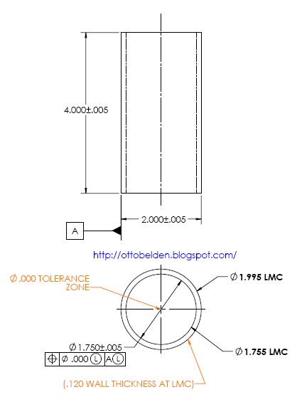
The I.D is the first thing that you measure and it's at the LMC dimension like above. In this case the I.D and the O.D are at LMC conditions as stated in the Feature Control Frame. The wall thickness is at it's worst case thickness of .120. It can't get thinner than this!

Now measure the last part in the box. this one comes out looking like the above picture. With both dimensions at MMC the wall thickness is nominally at .130 but with the tolerance of position the worst case is at .120. So using Positional Tolerance at LMC makes sure that the wall thickness can't get too thin.
The real power of using True Positoin and MMC or LMC is that it allows you as the designer to control one features position in relation to another features size. Being able to relate the size of one feature into another feature's size allows you to express the intent of the design into the drawing without having to use notes or other obscure methods. You don't have to say "When this is small that must be big" or "this has to fit something else..." all of the information necessary to manufacture the part correctly is expressed clearly on the drawing.
Please leave a comment or email me and let me know if you have any questions!
Otto
ReplyDeleteI have a square block where the tolerence is specied for the perpendicularity to be 0.00 at MMC. Is this possible? And what does this mean?
Thanks
Sameer
Sameer,
ReplyDeleteA zero tolerance at MMC is possible and relatively common. In the case of your block there should be some tolerance of angle someplace on the drawing. Frequently it's in the title block with something like "Unless otherwise specified angles +/- 1.0°" or something like that.
A zero tolerance of perpendicularity would mean that if the part or that particular feature is made at MMC it has to be perfectly perpendicular. If the part (or feature) is made under MMC a little bit then it can be out of perpendicular a little bit.
With your block if the angular tolerance is +/- 1.0 degree then at MMC it has to be perfectly perpendicular if the part is at LMC it can be out of perpendicular by 2 degrees (+/- 1° = 2° total).
I hope that helps! Let me know if that doesn't make sense.
- Otto
I consider that I good method to impose any drawing users to understand modifier M into a geometric tolerance is to specify a zero tolerance with a functional tolerance applied on the feature of size. He or she will to sit down and understand the concept and its application. After that most of them say :Thank you for the additional tolerance
ReplyDeleteGFGDT
Anonymous,
DeleteGreat idea to use the M with a zero tolerance where needed. It does make people stop and think and you probably get better parts that way.
- Otto